
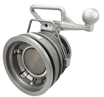
In this blog we will demonstrate how simple the 5500-series API coupler is to break down, service, rebuild, and return to service. A routine maintenance schedule will ensure the safe and correct function of the coupler.
A few things to note before defining the rebuild steps. First, there are no special tools or products required, however, there are a few basic items you will need to have on hand before beginning, they include:
- Needle-nose pliers
- 7/16 wrench
- 5/32 Allen wrench
- O-ring pick
- Coupler nose ring (part # 5204K3)
- Lithium grease
There are three recommended basic maintenance schedules for the 5500-Series API coupler. An inspection provides an opportunity to clean the coupler, look for cracks, deformities, and any irregularities of the components and seals. Any time these things exist, the components and/or seals must be replaced immediately to avoid leaks or coupler failure.
Yearly inspection includes:
- Examining all O-rings, the nose seal, the dust seal, the handle, and the handle bearing
- Examining the valve assembly which includes the bent links, poppet, link pins, and drive link. Any deformation in these items can cause premature failure of the coupler.
- Examining the shaft and handle assembly
Every two-years inspection includes:
- Examining all seals, they should be replaced regardless of their condition as part of a preventive maintenance schedule
- Inspecting and cleaning the coupler and any mechanical moving parts including the bent links, poppet, link pins, and drive link. Replace if necessary.
Every four-years inspection includes:
- Breaking down, cleaning, inspecting for damage to the entire coupler. All seals and broken/deformed components should be replaced. Components include the poppet, link pins, drive link, shaft, release, bail, sleeve, all cams, and springs.
Disassembly
Tip: When taking the coupler apart lay the components down exactly as you take them apart. This will save any confusion later during the rebuild process. i.e. putting the handle or bail on backwards.
Step 1:
The first step in disassembly is on the front end of the coupler. Notice the locking latch mechanism and the locking cams; you will need to engage all of these in order to open the coupler. Depress the locking latch mechanism working around all the locking cams until the coupler is in the open position. Engage the interlock latch while also engaging each interlocking cam – this will allow the spring-loaded collar to move forward and the coupler to be opened.
CAUTION: Keep your hands on the inside of the coupler and your fingers clear of the collar moving forward to avoid pinching!

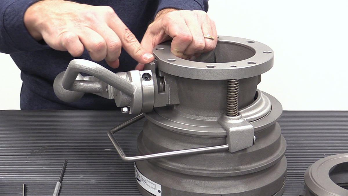
Step 2:
Remove the stainless steel cotter pin from the shaft using the needle-nose pliers. Once the cotter pin is straightened out open the coupler by rotating the handle counterclockwise so that you can pull the pin out. Remove the shaft cotter pin. At this point, you can remove the entire pin and handle assembly.

Step 3:
Remove the handle and bearing assembly. When you do this the entire yoke will fall through the front of the valve. The handle assembly includes a handle, shaft, bearing assembly, a locking plate, and a sleeve lock. The sleeve lock mechanism prevents the coupler from opening in the event of a pin shear.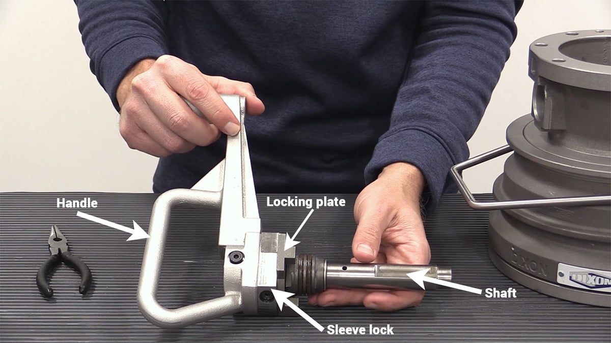

You must take the handle assembly apart by removing the handle, pulling the sleeve lock off, and removing the entire bearing assembly in order to get to the handle O-ring.
This assembly consists of three O-rings. To access the handle O-ring, you must remove the locking sleeve bolts and the handle, then slide the bearing assembly forward. If you ever need to remove the bearing assembly for repair it is important to note that it only comes off the shaft one way. The shaft is machined down and has a stop and washer that prevents the bearing assembly from riding too far down.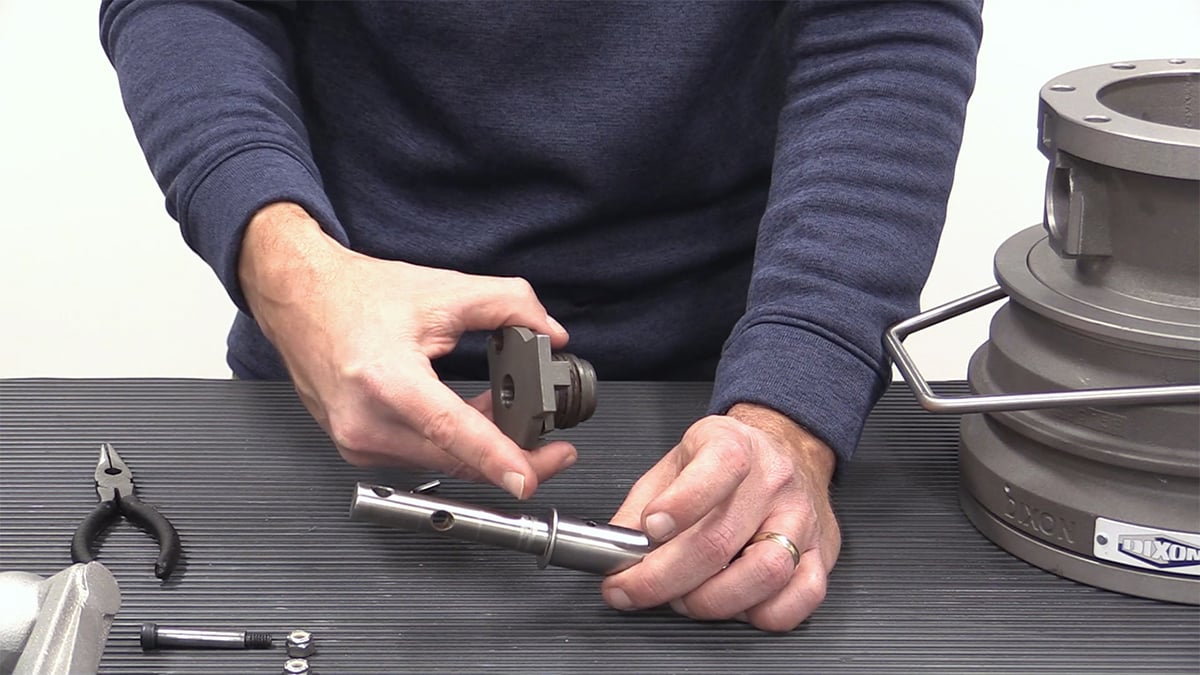

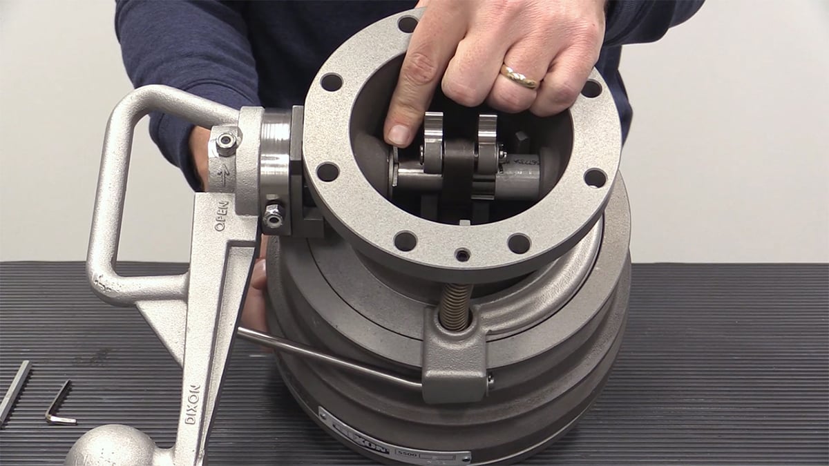
Step 4:
The next step in full disassembly is to pick up the coupler revealing the poppet assembly. The assembly consists of:
- Nose seal
- Dust seal
- O-ring
- Bent link
- Drive link
- Link pins
- Shaft spacer
- Shaft inside washer
The poppet assembly consists of a felt dust seal, an O-ring, and a face seal. The face, felt, and O-ring seals can be easily removed from the machined groove by using an O-ring pick. Be very careful not to mar the surface of the poppet when removing the seals. A damaged surface can create a leak path.

Inspection of the bent link, drive link, and link pins is important at every inspection interval. If they are deformed or cracked, they need to be replaced.

The bent links can be easily removed by removing the stainless steel cotter pin and the washer. Next, take out and inspect the bent link pin. If any deformation is observed the pin(s) must be replaced. Any damage to these pins could potentially cause a premature failure in the coupler. Set the poppet assembly aside.
Step 5:
Next, to get to the release remove the stainless steel cotter pins and washers on either side of the release, then remove the release.

Step 6:
Use the 5/32 Allen wrench to remove the screws so you can access and remove the bail pins and bail springs. Turn the coupler over and the pins will fall out; set them aside. Next, remove the springs; be careful as you compress and pull them that you hold on to them.

Step 7:
Remove the bail.

Final Step in Disassembly:
Remove the sleeve by pulling it up and over the TTMA flange revealing the rest of the coupler. Notice locking cams and springs on the backside of the coupler; these are very easy to replace if it is determined to be necessary. Simply remove the cams, and stainless compression springs by pulling them out with needle-nose pliers. There is also an additional felt dust seal on the outside of the coupler that should be inspected and replaced if needed.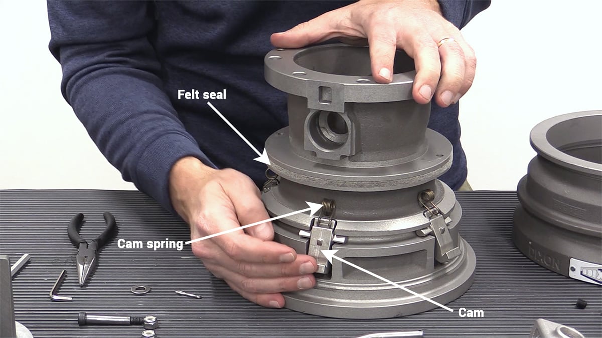

Inside the coupler are 10 stainless steel coil springs. The springs sit inside a tapered hole that holds them securely in place. They can be easily pulled out, again, by using a pair of needle-nose pliers.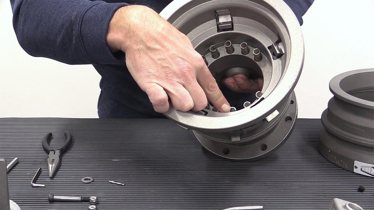

Tip: When putting the coil springs back in place insert them counterclockwise, because the springs are in a tapered position, they will sit in the recess a little easier by using this tip.
Reassembly
To reassemble the coupler, simply put the coupler together in reverse order, starting with the interlocking cams, springs, and compression springs.
Tip: Reassembly will require the use of the API nose ring (part # 5204K3) to engage the interlocking cams and allow the sleeve to travel forward.
Step 1:
Put the sleeve over the assembly. Note the sleeve will not sit all the way down. A tip that will help to re-engage the sleeve is to use an older nose piece (part # 5204K3) from a 5204-Series API coupler. These nose pieces are readily available from fleets because they change them out on a regular basis, and they should be easy to obtain. You will need this nose piece to be able to engage the locking mechanism and all the cams simultaneously. Set the sleeve and poppet assembly on top of the nose piece and then press the sleeve into the forward position.

Step 2:
Next, put the bail back on the coupler, put the bail springs in place, drop the bail pins in and then put the bail screws in place, and tighten them snugly using the 5/32 Allen wrench. Be careful not to overtighten them.

Step 3:
Add the release mechanism, once it is in place put the washers on and reinstall the stainless steel cotter pins using the needle-nose pliers. At this point in the reassembly process, you will need to pull the release towards you to remove the nose ring (part # 5204K3). You must remove this now because you will not be able to get the poppet assembly in place through the nose ring.

Step 4:
Turn the coupler over and depress the locking latch walking around all the locking cams; the coupler sleeve is in the forward position and is ready for the next step.
Step 5:
During handle assembly make sure the hole for the long bolt in the sleeve lock is facing away from you, if it is facing toward you the holes will not align. Once the sleeve lock is attached attach the handle next using the 7/16 wrench and the 5/32 Allen wrench to tighten the assembly.
Final Step in Re-Assembly:
Next, drop the coupler over the poppet assembly. Insert the handle, before passing it through the drive link put the shaft washer in place, then pick up the drive link and insert it, next put the shaft spacer in. The locking plate has a machined square notch that you need to push in place. Now put the stainless steel cotter pin in place, rotate the handle clockwise holding the pin in place with your finger, and bend the cotter pin back in place using the needle-nose pliers.

Your 5500-Series API coupler is now fully assembled.
Click to watch our complete rebuild video.
If you have questions or want to learn more about the 5500-Series API couplers, please contact a specialist at 513.874.8499 or visit dixonvalve.com