
There are many variables to take into consideration when selecting and designing a loading arm. The configuration, components, applications, measurements, media and site limitations, all must be taken into account for the design. Being able to work through this process in a clear concise manner will ensure that all these variables will be considered in the final build of your loading arm.
Configuration
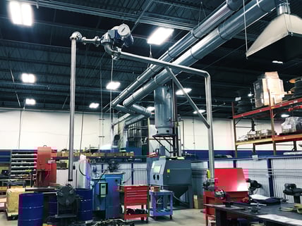
The first decision to make when selecting a loading arm is the configuration. The typical configurations are a-frame or horizontal. It is common for top loading applications, whether for drums, totes, railcars or over the road trailers, to use horizontal style arms. Alternatively, if the media conveyed is pumped into the bottom of a container truck and filled from the bottom, an A-frame style loading arm is typical installed. We also offer custom styles, sizes and configurations beyond just the standard a-frame or horizontal including scissor style, downfeed, etc.
After deciding on your style the next step is to select upfeed or downfeed. This is typically dictated if the onsite plumbing is pumped from the ceiling or canopy of the loading terminal or up from the ground.
Then choosing left-hand or right-hand counterbalance mechanisms. This is going to depend on how your environment is set up. A quick tip is to use left-hand and right-hand configurations next to each other because they can pivot closer together and won’t interfere with each other due to the cantilevered design.
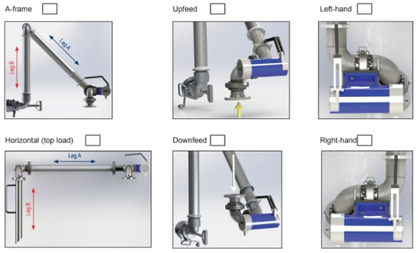 Above: A screen shot from our easy to use Loading Arm Order Guide.
Component Measurement and Material
Now that the configuration has been decided, selecting the measurements and material is next. Each leg of your loading arm will need to be measured from center of swivel to center of swivel to the nearest foot. Leg A is from the counterweight end to the swivel. Leg B is from the swivel to the coupler end. Materials for each leg could be carbon steel, aluminum, or stainless steel and leg B could also be metal hose. The loading arm media will help decide which material is used for each arm based on chemical compatibility and other factors such as the strength of the material. Most times they are all the same material for horizontal loading arms, however leg B on a-frame loading arms are typically a composite hose or metal hose to allow flexibility in connection points.
Application Information
Now the application will be used to select the rest of the options for the loading arm. What pipe size is required? Typically this selection will be driven by your current setup or flow requirements (GPM). What type of base swivel style (split flange, v-ring or o-ring) will be needed on the loading arm? What type of connection is required on your riser stand pipe: 150 ANSI flange, 300 ANSI flange, TTMA flange or other? This will depend on your current set up, but most arms that we’ve built have been 150 pound flange.
Also dictated by the application, more specifically by the mating end connection of the vessel the loading arm is intended to fill, is the outlet or end connection of the arm. In many cases top loading applications will end with an open pipe cut at a 45-degree angled drip edge or a diffuser. In many cases bottom loading assemblies will use an API coupler to ensure a leak proof connection. While those options are common it is not unusual for loading arms to utilize many other standard couplings found in the Dixon product offering. These include Cam & Groove, Dry Disconnect, Vapor Recovery fittings and more.
For seal selection you can request a seal material such as: buna-N, Viton™, PTFE, FKM A&B, or EPDM, or you can refer to your loading arm specialist to select the proper seal based on your application. Often the temperature of the media and chemical compatibility of the seal material with the media dictates what seals should be used.
Site Limitations
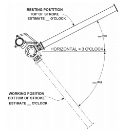
Now that the loading arm is built, it’s important to verify that it will fit properly at your site. Providing your loading arm specialists with any site restrictions will ensure the best fit of your loading arm. The ceiling or roof height from the riser pipe connection distance will ensure that the loading arm will not come into contact with the building. If there are any additional items that add weight that should be accounted for when building your loading arm. A few examples include: vapor hoses, drip buckets, hold-down chains, etc. The range of motion desired is important to discuss prior to the build so we can make sure the arm will provide the motion required for the application. The range of motion can be explained using the clock method (see below).
 Above: A screenshot from our easy to use Loading Arm Order Guide.
Sketches/Notes
If there are any additional notes or sketches required providing that will also be helpful to the loading arm specialists. “Pictures are worth 1000 words” so please provide pictures if available and site conditions allowed (for example some facilities require intrinsically safe electronics).
Conclusion
There are many advantages to using loading arms. Safety can be improved and repetitive tasks can become easier for the employees. Relying on your loading arm specialist to verify the design and manufacture your loading arm will ensure a successful product. Our team of loading arm specialists are always here to help design your application. If you don’t see the options that you need reach out to our  to discuss custom options. We have a quick order guide to make this process simple, which works through the steps above.
If you have questions we are here to help.  .
.